In the case of ORMA 60s and A cats, the hulls have such favorable drag characteristics that ‘foiling’ does not (yet) pay in the majority of conditions. Instead, boards already present to provide side force are modified and ‘double purposed’ to complement the buoyancy of the displacement hull. This is a ‘foil assisted’ mode.
 |
| ORMA 60 in flat water. Notice the forward location of the foil and the bow-up attitude it encourages. Image source: www.sail-world.com |
Hull drag vs. dedicated foils (additional foils for generating vertical lift)For every length traveled, a conventional hull must displace (move out of the way) an amount of water weighing the same as the boat.
A long slender hull with a fine entry angle, narrow beam, and shallow draft, can spread this displacement ‘thinly’ over its length, effectively making a very small hole in the water.
A long slender hull with a fine entry angle, narrow beam, and shallow draft, can spread this displacement ‘thinly’ over its length, effectively making a very small hole in the water.
The water pushed out of the way at the front takes energy away in the form of a bow wave. Some of this energy is recovered when the second peak of the wave system forms at the stern, effectively leveling the hull.
The net loss of energy (wave drag) increases rapidly as speed approaches and exceeds ‘hull speed’ – hull speed being the speed characteristic of a wave with the same length as the hull. For very slender hulls the drag rise with speed is more linear but still steep.
The net loss of energy (wave drag) increases rapidly as speed approaches and exceeds ‘hull speed’ – hull speed being the speed characteristic of a wave with the same length as the hull. For very slender hulls the drag rise with speed is more linear but still steep.
Lift generated by foils comes with its own drag penalty. Think of it as a cost that has to be paid to get the lift. Foil drag has several components such as lift induced drag – proportional to the lift generated – and profile drag – always present as a consequence of the foil being in the flow.
At low speeds the drag associated with supporting all the weight of the boat with foil vertical lift is much higher than the drag of a long slender hull cutting through the water.
As discussed previously, wave drag as a component of total hull drag is of lower relative importance in a multihull than surface friction drag – which is proportional to wetted area and rises less steeply with speed. But when comparing hull drag with foil drag, we look at the total drag for each alternative, assuming each has been optimised with respect to its components.
As speed rises, hull drag generally rises more steeply than does the drag of the ideal foil for that speed.
This is a complex tradeoff, taking into account that a smaller foil can do the same job at higher speeds – the ideal foil size gets smaller with rising speed.
At low speeds, foils would have to work very hard to impart on the passing water the circulation necessary to generate sufficient vertical lift to support the weight of the boat. Or they would have to be larger, with higher parasitic drag and more area than would be optimum at higher speeds.
At low speeds, foils would have to work very hard to impart on the passing water the circulation necessary to generate sufficient vertical lift to support the weight of the boat. Or they would have to be larger, with higher parasitic drag and more area than would be optimum at higher speeds.
Crossovers
For every boat type there will be a crossover speed where foil drag goes from being greater than hull drag to being equivalent and eventually smaller. Think of it as hull drag overtaking foil drag as speed rises.
In the case of a long, slender, light boat such, that speed may be seldom reached during racing. In any case, sizing of the foils for the ideal crossover speed may be problematic if such dedicated foils would be of little use at other speeds.
In the case of a long, slender, light boat such, that speed may be seldom reached during racing. In any case, sizing of the foils for the ideal crossover speed may be problematic if such dedicated foils would be of little use at other speeds.
If T or L/J foils were used, separating out the task of generating vertical lift from that of providing side force, then the sizing of the horizontal foils (or foil segment in the case of L/J foils) would be such that the parasitic drag at low speeds would be crippling, and/or efficiency at high speeds would be compromised. This is before taking into account ride height control, stability in pitch and the effects on righting moment.
 |
| J and T foils separate the vertical and horizontal lift functions to different parts of the foil. Thus vertical lift can be independent of side force and only related to speed and angle of attack, but there is a penalty in terms of parasitic drag because foil area is increased |
Using existing foils (necessary to generate sideforce) to provide some vertical lift
Using angled or curved foils results in less parasitic drag but an important constraint exists because sideforce is ‘pegged’ to sail force.
Because vertical lift is one component of the total foil force, its relationship to sideforce is fixed. An approximation of this fixed relationship is given by the dihedral angle of the foil.
Dihedral angle for an angled foil is simply the ratio of vertical projection to horizontal projection.
If the foil were angled at 45 degrees, then the two projections would be equal. In this case horizontal lift would equal vertical lift at all times.
Ignoring flow peculiarities due to foil curvature, the effective dihedral angle of a curved foil can also be approximated by looking at horizontal and vertical projections.
 |
| Dihedral angle determines the ratio of horizontal to vertical component for a given foil force. Note that since the two components are in a fixed ratio for a given dihedral angle, and since sideforce is determined by sail force, the amount of vertical force ftom a curved or angled foil will always be limited by sail force |
Break-even points in different cases
A long slender hull with high efficiency in terms of wave drag, and minimum wetted area, may be a better solution around a course than any hydrofoil geometry that aims to completely replace displacement with vertical lift.
The two extremes are easy to calculate:
A long slender hull with high efficiency in terms of wave drag, and minimum wetted area, may be a better solution around a course than any hydrofoil geometry that aims to completely replace displacement with vertical lift.
The two extremes are easy to calculate:
At low speeds the hulls are supporting all the weight by displacing water and the foils are ‘coming along for the ride’, generating parasitic drag.
At foiling speeds the hulls have zero hydrodynamic drag (they are out of the water) whilst the foils have friction drag and lift induced drag as well as losses due to any loaded surface piercing parts.
The transition period is more complex because as lift from the foils increases, the hull has to displace less water (it gets ‘lighter’).
This actually increases the efficiency of the hull because it makes it even lighter for its length.
But the reduced hull drag must be weighed against the foil drag.
This actually increases the efficiency of the hull because it makes it even lighter for its length.
But the reduced hull drag must be weighed against the foil drag.
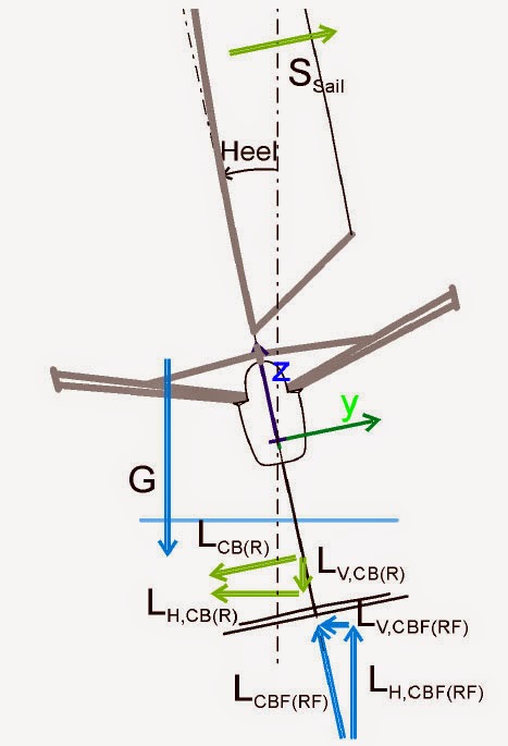 |
| Forces on a foiling moth. Note that the submerged horizontal foil provides a force with both horizontal (side force) and vertical components. Diagram taken from www.moth-sailing.org/download/10-11-11_ThesisBoegle.pdf |
Contrast this with the case of a moth: a short relatively heavy boat (when taken with the weight of the crew) where hull drag is much more expensive, so the crossover with lifting foils happens lower down the speed range.
Even then, compromises have to be made in light winds.
Even then, compromises have to be made in light winds.
But the contrast is even starker when you consider that foiling moths are able to heel to windward.
This allows them to use the fully submerged horizontal foil to provide both side force (horizontal component) and upward lift (vertical component).
The horizontal foil, free of surface interference, then effectively becomes the fulcrum and every other part of the boat is providing righting moment.
It is interesting that even a moth does not use separate dedicated foils for vertical and horizontal lift but instead combines the components in a single efficient surface.
Such a solution probably could not work well on a multihull with foils mounted outboard (heeling to windward would be possible but it would not result in similar gains).
Once again, a long slender hull is much more attractive in terms of drag than complex foil geometries.
Re-purposing existing foils will be better at certain speeds. The challenge is finding the crossover that gives minimum time around the course. What has been proven to work
Having said all the above, curved foils that assist displacement hulls do work around the racecourse.
This is mainly because they increase hull efficiency with a drag penalty that is much smaller than what would be incurred by a fully foiling arrangement.
There is a subtle ‘sweet spot’ where the existing board (as opposed to a separate dedicated foil) is only generating marginally more lift than it would be if it were vertical (the total foil force must increase if the vertical component is to increase) so the additional drag is small.
In doing so, it supports some of the displacement, effectively making the hull lighter.
The hull stays in the water so all the waterline length is still being used, but now the displacement to length ratio is even better.
There is also a bow up trimming moment that results from the foil being in front of the centre of gravity. This is effectively like making the bow fuller without changing the hull entry angle.
But to get a better understanding of the complexities involved, we have to look at the effects on righting moment, stability in pitch, and ride height control.