
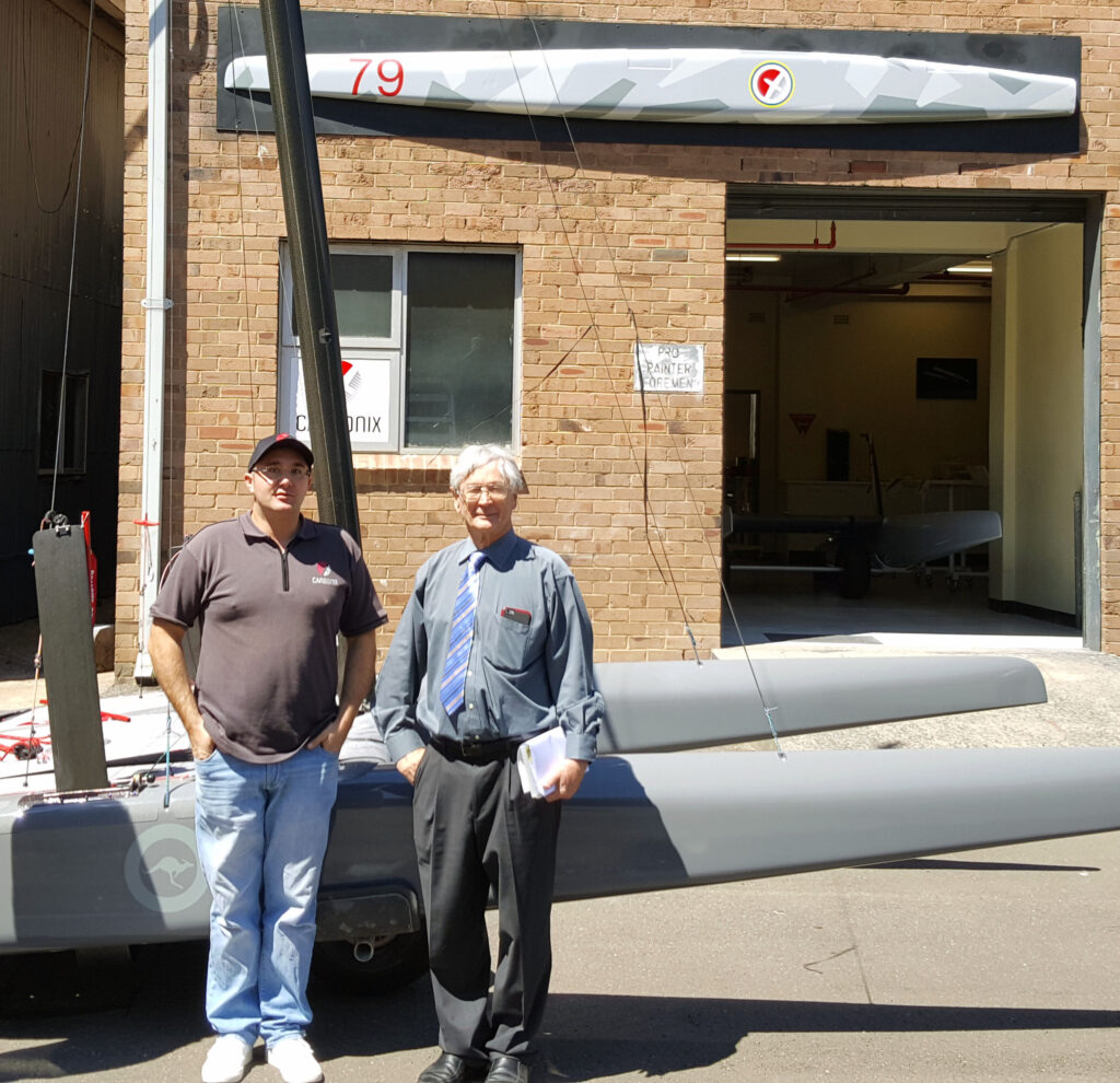
Apple co-founder Steve Wozniak took an interest in the Carbonix Volanti VTOL RPAS at a recent tech community event..
Fascinating to hear him relate how the current rapid development in UAV technology “must feel like” the early days of the PC.
Those directly involved had an inkling of the potential this new technology promised, but new applications kept popping up seemingly every day.


Airframe Development, A Path of Continuous Improvement
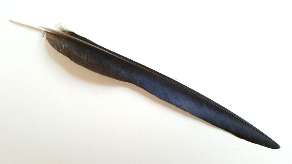
At Carbonix we are passionate about sharing what we do with those who are similarly fascinated by high performance materials and fluid dynamics. Advancing the state-of-the art is an absorbing process of interrogating nature, testing new ideas, and learning through observation. We know we are not the only ones hooked on the beauty of foils, wings, and elegant design. Communicating our journey is a great way to engage with the wider community.
First Applications
As early as 2010, customers aware of our work in high-performance sailboats approached us to apply our knowledge and processes to airframes. Our resulting initial forays into developing remotely piloted aircraft taught us some very interesting lessons about the parallels between sailboats and airplanes.
We have always valued designing from a set of requirements – identifying the customer’s needs (both technical and budgetary), then developing solutions to suit. Whether working from class rules that may specify length, beam, and minimum weight; from a set of downforce figures for a race car; or from payload and range numbers for a plane… The process is always one of evaluating key factors and then finding the right point in the design space.
Though each application has its own characteristic complexities and challenges, racing sailboats tend to require extraordinary versatility: Their foils (wings in the water) and sails (vertical wings) must work over a widely varying range of conditions and hence characteristic flow regimes. Since the power source is variable, the loads and speeds involved change dramatically. The ideal shapes and structural solutions for sailing in light breeze and flat water (underpowered) are very different from what’s needed in strong winds and big waves (overpowered). Yet the designer must tread a middle-ground accommodating both extremes and correctly identifying the solutions that are most advantageous overall.
The brief for an aircraft might specify a minimum flying speed, range requirement, and some inferred key speeds related to achieving the desired mission objectives efficiently. Overall weight will be within known bounds, changing predictably with fuel consumption and payload configuration (for instance a minimum and maximum number of passengers, or dropping off a known cargo mass). Power is usually known quite precisely, and can be controlled at will.
Our experience with racing sailboats, and the resulting methods and evaluation tools we have amassed, allow us to confidently tackle complex aircraft briefs. Our recent pioneering work with vertical take-off airframes is a case in point: The resulting aircraft types can deal efficiently with an extraordinary performance envelope that goes from zero airspeed (even flying backwards at times) to very slow loiter, to fast cruise. All with varying fuel loads and payloads.

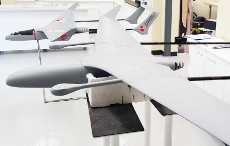
Cometa
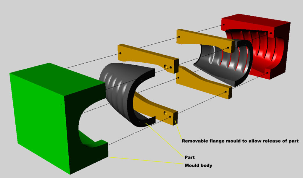
In 2013 D3 Applied Technologies approached us to build their Cometa design. D3 has world-leading expertise in designing and analysing efficient aerodynamic structures for applications as varied as fishing vessels, turbine blades, and even buildings. Our role was to design and build the tooling as well as develop detailing and hardware solutions for prototyping and productionising the new UAV. We built the first prototype based on engineering work carried out by Gurit in collaboration with D3 and Carbonix.
After completing test parts and the first prototype, we undertook a process of development and optimisation for the tooling, construction method, structural arrangements, laminates, fittings, and detailing. At this scale, physical testing of parts is practical and economical, so the process was very hands-on and iterative. More finished prototypes were produced, with measurable improvements across several key areas. While the shape designed by D3 only underwent minor changes, significant gains were made in the build process and structural layout. The main areas of focus were reducing labour content with reliable reproducibility, and achieving optimum aeroelastic behaviour of the loaded structure in flight.
Following are some points of interest and key lessons and changes. A brief look at some milestones on the winding development road.
Structural Optimisation
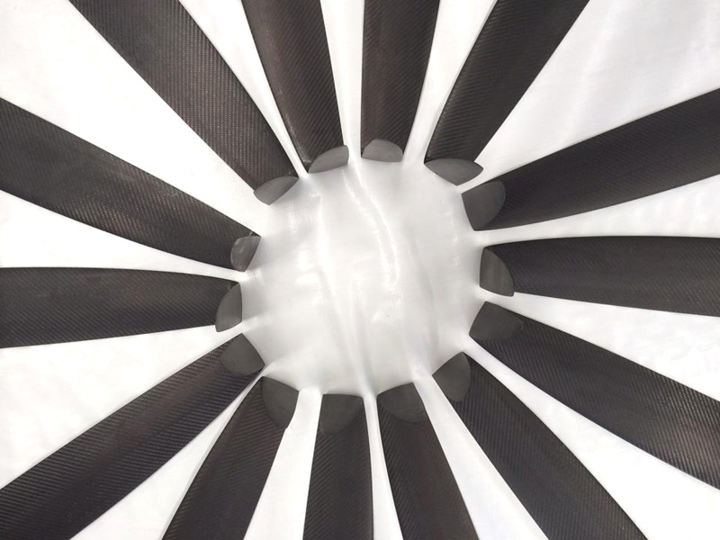
Different arrangements were tested for the main spar construction and monocoque skin laminates. The main candidates were: A shaped foam main spar with thin skins, a tubular spar, and variations on I, Z, and C beam section moulded spars. As well as deflection under load and overall weight, factors such as labour time required for assembly, tooling costs, and downstream impacts on the resilience of the skins were considered.
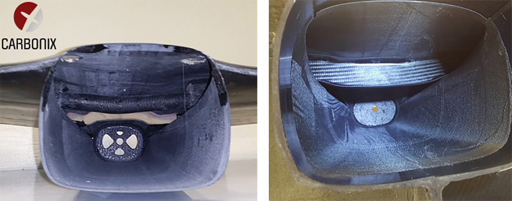
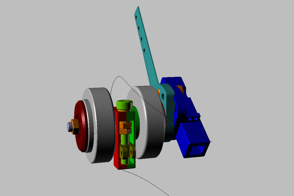
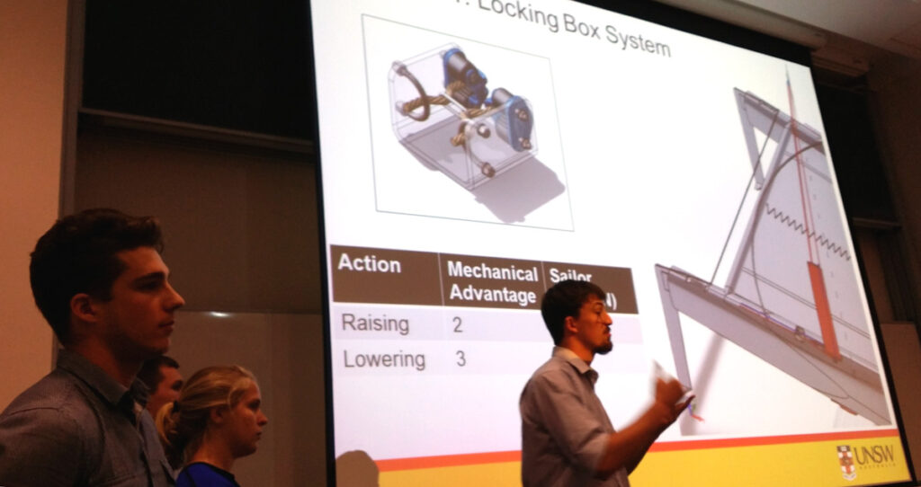
Since the airframe is modular and comes apart for packing into a compact transport case, we identified some great opportunities for making gains through innovative solutions for the various interfaces and joints. The outer wings unplug at roughly one-third span, near the root of the longitudinal booms. So an effective spar joining method had to be devised to transfer the bending moment and locate the outer wing securely. After testing various configurations of axial screws, transverse pins, and even magnets, we developed and optimised the T-Latch system that allows secure, tool-free assembly without needing access to the inside of the airframe, and leaving a flush surface on the wing.

Similarly we developed quick-release systems for the tail-booms and various options for securing the payload bay and internal shelves. Such structural details and fittings enhance usability in the field and complete the look and feel of the airframe as a premium product for commercial use.

Launch Method – CTOL to VTOL
The initial brief was for applications where ground equipment would be available (flying out of dedicated bases in fixed locations). So to minimise on-board weight and complexity a catapult-launch and parachute-land system was selected. For initial testing the D3 Cometa design also incorporated removable tricycle landing gear. Combined with flaps, this would allow the option of conventional landing at very low speed, minimising the chance of damage.

When Carbonix explored commercial applications of this airframe and upcoming new models, it became apparent that the ability to launch and retrieve from small unprepared areas (often flanked by obstacles such as trees or cliffs) was very important to customers. Being able to slow to a hover mid-mission was also evidently desirable. And having the redundancy associated with a vertical flight system was also an attractive feature.
We identified a clear gap in the market for small and medium UAVs combining the long range/endurance of a sophisticated fixed-wing aircraft with the versatility and agility of a multirotor. Therefore Carbonix undertook R&D with both short-term and long-term goals.
We are developing an all-new airframe at the upper range of the 25Kg weight category with vertical take-off and landing (VTOL) capability designed-in from the outset. This airframe will be aimed at extended and beyond visual line of sight (BVLoS) operations. Thus it will have the carrying capacity to accommodate safety equipment as required to integrate and communicate with other airspace users.
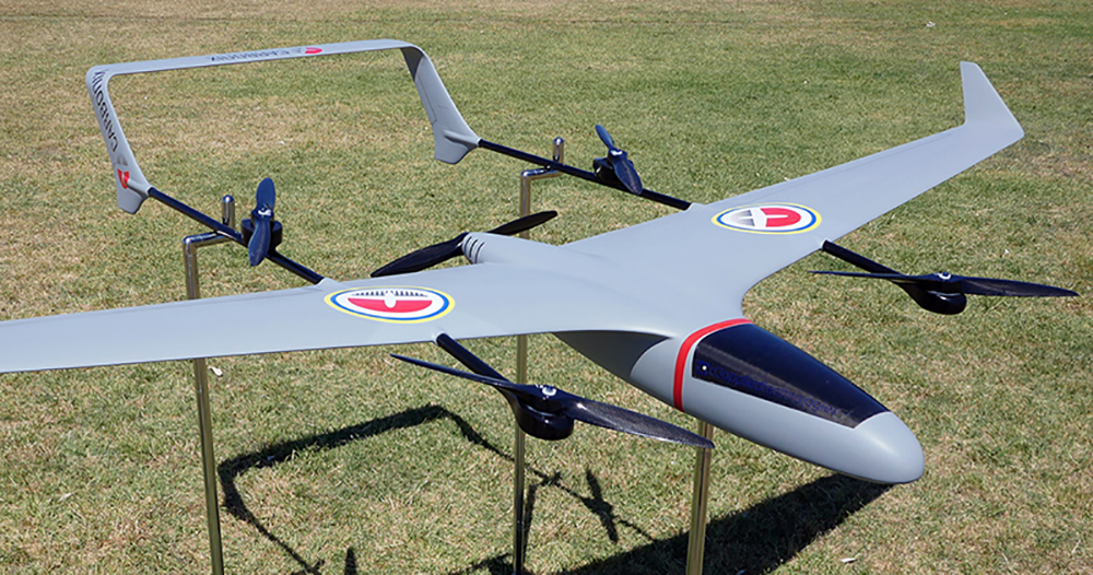
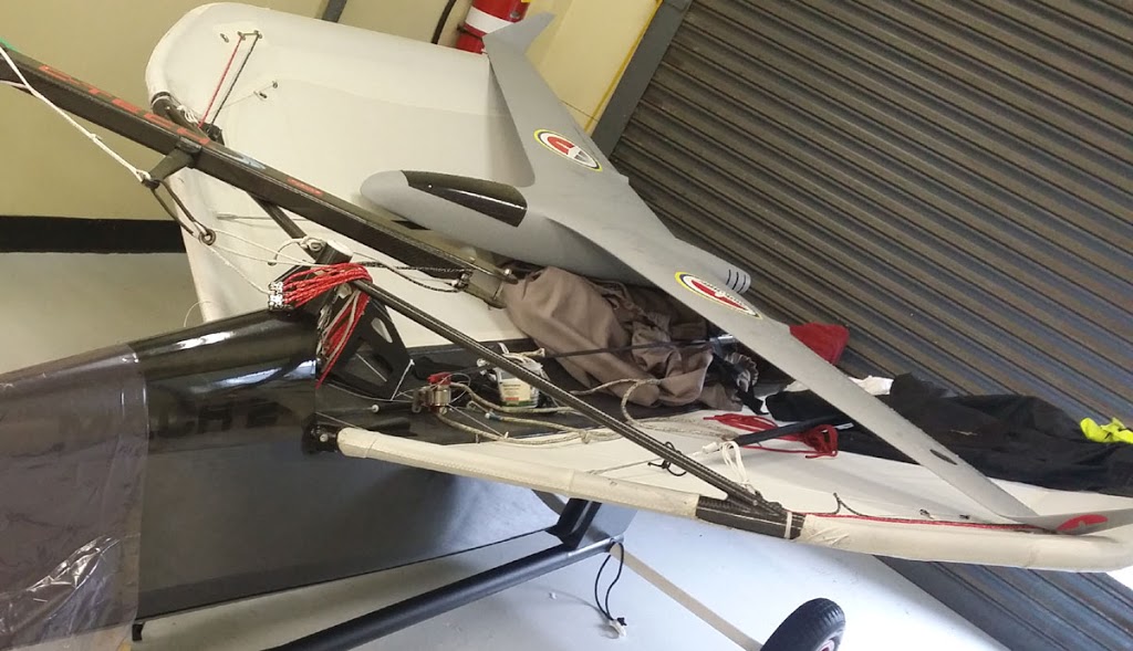
Short term, and to satisfy demand in the 10Kg to 15Kg weight range, Carbonix worked extensively to create a variant of the D3 designed Cometa with added VTOL capability. In the process delivering the first commercially available fixed-wing/VTOL hybrid made in Australia.
Selecting a VTOL configuration for a fixed-wing aircraft is a wonderfully nuanced challenge. The basic trade-off comes down to the following: Do you use the same motors and rotate their orientation between horizontal and vertical flight? Or do you keep the two systems separate and carry dedicated motors for each flight mode?
On the face of it, using common motors seems attractive to the elegance-seeking designer because it does both jobs using fewer elements. However, on close analysis the compromises are subtler. If we look at part count carefully, we must include the actuators needed to rotate the motors, and some means of changing propeller pitch to accommodate the difference between the low-axial-airspeed/high-power vertical regime and the high-axial-airspeed/low-power mode needed in horizontal flight. Add the fact that a dedicated horizontal flight motor can be optimised for range/endurance (for example it can optionally be petrol-powered and have a fixed-pitch propeller optimised for loiter or cruise), and the decision looks like it could go either way.
This is where expertise in evaluating design solutions to the specific brief, and quantifying such pros and cons really gives us an advantage. We advocate a disciplined, numbers-driven approach, informed by design intuition. Always guided by the values of wanting to create beautiful solutions.


It should be obvious from the above that not all applications call for the same solution. Variables such as overall weight and the percentage of mission time spent in vertical flight can tip the balance one way or the other. For example, our upcoming larger airframe could well use tilting motors in one alternative configuration. The aim is always to offer the best solution to suit the mission. Flexibility and modularity are vital as one size will not always fit all.


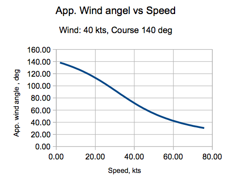
The diagram below nicely illustrates what happens as speed builds.
The plot takes a constant true wind angle (heading relative to true wind direction). As boatspeed increases, the component of apparent wind from dead-ahead gets bigger, while the true wind velocity stays constant. Therefore the wind we feel on our sail moves progressively further forward.
 |
| Diagram taken from the interesting article here: http://boards.co.uk/how-to/how-fast-can-we-go-the-science-of-speed.html#AmZd7dgCcvAEmL31.97 |
As apparent wind direction moves forward, we have to sheet on in order to keep an angle of incidence between sail and apparent wind. But moving the boom closer to the centreline increases the component of sail force that wants to heel the boat over. For the same sail force, drive decreases and overturning moment increases. Hence we need righting moment to resist the added heeling moment.
 |
| On the left we have the boom eased and the sail twisted. Sail force (orange) is mostly directed forward. On the right the boom is near centreline and the leech is tightened by sheeting on. In these diagrams sail force is identical but the component to leeward (responsible for heeling moment) is much larger when the apparent wind rotates forward. In reality, when the apparent moves forward, it also increases in speed. So sail force would be larger, exacerbating the problem. |
Recent work with AC45 Turbo test platforms, and smaller cats, has shown that differential rudder rake, such that the windward elevator foil produces downforce, can add significant speed.
It may be that using the windward foil to pull down could pay, bringing about a return to four-point systems.
But it is certain that span restrictions that require multiple surfaces to get sufficient lift on the leeward side are driving development to a dead-end. If such restrictions persist, more changes are inevitable as people invent elaborate rule-cheats such as having several foils in each hull.
Much better to encourage simplicity.
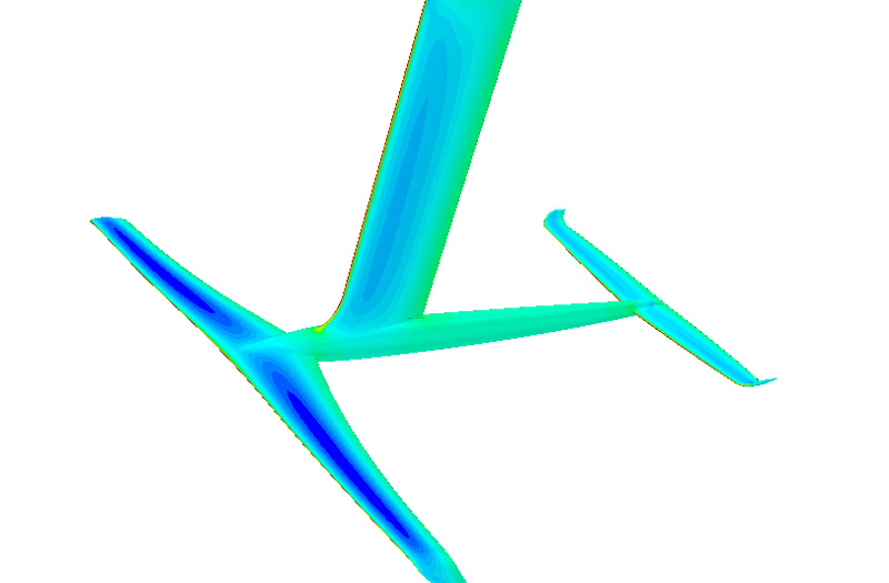
He used (for the first time) an all-new foil package (vertical, fuselage, and horizontals) created with project and design co-ordination by Carbonix. CFD and optimisation was by d3 Applied Technologies. Tooling design by Carbonix…


 |
| Pic courtesy Sentient Blue Team showing a 2007 A Class platform retrofitted with Carbonix 2014 foils and rudders. |
Specifically, we worked to gain data on how different foil configurations affect dynamic behaviour during turns in strong wind.
The results confirmed observations we hear regularly from experienced Moth sailors, as well as those who race foiling multihulls such as the NACRA F20 Carbon FCS:
Being foilborne on the upwind leg makes the bearaway a lot safer.
Intuitively it is easy to understand that a foil has the ability to ‘push back’ with increasing force as the bow-down moment from the rig increases. But this is only part of the picture.
In displacement mode, an increase in bow-down trimming moment must result in some bow-down trim in order to move the centre of buoyancy forward.
More volume has to be displaced closer to the bow so that a restoring bow-up moment can exist to counter the increasing bow-down moment from the rig (which in turn is a result of sail force increasing and rotating to point more forward during the bearaway).
A secondary effect of the bow-down trim is that the rig increasingly pushes down, effectively increasing displacement.
All the while drag is increasing, speed is diminishing (or increasing at a reducing rate), and available volume (forward buyancy) is running out.
Staying on the foils instead allows the foil/elevator system to dynamically counter the changing sail vector.
Less obvious, and possibly more important, is the fact that, with less drag and smoother acceleration, the apparent wind stays forward so bow-down trimming moment is much smaller.
To reap the benefit, foiling upwind has to be competitive.
This can only be the case when maximum righting moment is available.
To maximise righting moment the leeward foil must be able to carry the boat at moderate (upwind) speeds and give some heave stability unaided.
Safety is perhaps the most compelling argument for ending the absurd restrictions imposed on the A Class by a shrinking minority.


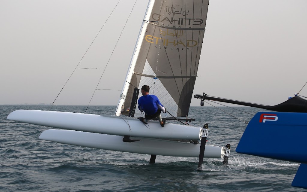
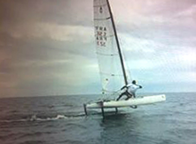
 |
| Images of customers who have retrofitted our L foils to existing (mostly older) A Class cats. A low-cost upgrade that increases performance and improves handling. Incidentally it makes beach launching easier, as the foils support the hulls, giving a small point of contact rather than potentially scratching a larger area. Obviously it is better to always use a set of ‘beach wheels’… But where laziness or circumstances do not allow it, the foils make for less widespread damage. |