This will be the last instalment on geometry and dynamics. I will cover structures and detailing in the next post.We saw that the boats are powered by a rig capable of large variations in lift coefficient. The cut of the sail and the flexibility of the streamlined mast are tuned with crew weight to achieve automatic gust response.
The platform is relatively narrow but is powerful due to the crew being on trapeze.
Hulls have very high length to displacement and length to beam ratios.
These characteristics make friction drag significant compared to wave making drag. The importance of friction drag places a premium on minimising wetted area.
Hull geometry must allow for the variation in displacement between sailing upright and flying a hull. The designer must weigh up the time spent in each mode and the exact transition speed.
A large range of positions of the centre of gravity (CG) is possible because the sailor accounts for over 50% of total displacement.
Angled or curved foils add an interesting new dimension:
They give rise to the problem of stability in pitch and ride height.
This problem has not yet convincingly been solved in a way proven on the racecourse.
It has instead been mitigated by designing in ‘reserves’ of stability and sailing the boats ‘around’ the limitations imposed by the inherent instabilities.
Hull shapes have been increasingly adapted to provide buoyancy and dynamic lift in the stern. Big sterns provide the bow down moment necessary to ‘store’ reserve bow up moment required to delay terminal feedback loops caused by instability in pitch and ride height.
In other words the bow down moment provided by wide, flat, buoyant sterns gives something to ‘trade’ when additional driving force needs to be reacted.
The price of this solution is additional wetted area.
Despite such adaptations, current designs must limit foil lift by increasing the foil radius (making the boards straighter) and/or partially retracting them at high speeds (reducing effective dihedral).
If the boat were stable in pitch and ride height, reserves of trimming moment and AoA would be unnecessary. The drag penalty associated with providing these reserves could be avoided.
The foils would automatically provide the necessary restoring moment (bow up or bow down) to counter perturbations caused by external forces such as waves and gusts.
There would no longer be a need to curtail foil lift at speed. Maximum advantage could be had from foil assistance.
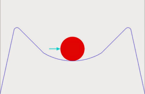
The following diagrams illustrate conceptually the difference between stable and unstable systems.


Above left is a representation of an unstable system: any disturbance (such as the arrow shown) will cause the red ball to roll down the curved hill further and further away from the starting point.
It is analogous to a situation where increased angle of attack (AoA) causes a pitch up which in turn increases AoA… Giving rise to a feedback loop that takes the system further and further away from the starting point.
Above right is an unstable system with a small neutral zone rather than a single equilibrium point.
Some force will displace the ball toward runaway instability but there is time to react.
The flat area represents the reserves of trimming moment and foil AoA provided by wide sterns on current A Cats.
Notice that when the force is removed the ball does not automatically return to the centre of the neutral zone. It must instead be returned there ‘manually’ or it will remain closer to one unstable limit than to the other. In this representation, actively keeping the ball away from the edges of runaway instability is equivalent to the active crew movements and changes in heading and sheet tension required when pushing hard downwind.

Above left is a representation of a stable system. The harder the ball is pushed away from the equilibrium point, the harder it pushes back.
When the upsetting influence is removed, the ball will return to the unique equilibrium point.
To the right we see a stable systems within limits.
This represents a conventional hull: It will resist changes in trim and sink by generating progressively more restoring force. But at a certain point it will give up and ‘flip’.
In the case of a conventional hull, this limit is approached when the bow is completely buried and the crew is right at the back.
The ideal foiling or foil assisted boat would also behave according to the last diagram.
If the reader will indulge me, I would briefly take a highly simplified look at aircraft theory to convey in more practical terms the idea of a dynamically stable system.

Above you can see the effects of varying pitch angle on the balance of forces on a conventional aircraft.
If the nose is pushed down, the initial small negative AoA on the tailplane increases. This pushes the back of the aircraft down harder. Thanks to the long lever arm provided by the fuselage/empennage, a level attitude is restored.
Conversely, if the nose were pushed up, the tailplane would be projected down. AoA on the horizontal tailplane would go through zero, then turn positive and continue to increase until sufficient upward lift is generated to automatically pull the tail back down.
This self levelling is completely automatic without pilot intervention and arises from the geometry of the flight surfaces.
It is distinct from manipulations of the control surfaces that the pilots may affect in order to change flight direction.
Stability can be calculated taking into account the relationships between wing area, tailplane area, and CG.
It is easy to see that the tailplane has sufficient leverage to control pitch attitude even with a modest area compared to the main wings.
In level flight the tailplane actually pulls down slightly. Small nose up perturbations at first cause this downward pull to go to zero. Further perturbations pushing the nose up then progressively increase positive angle of attack on the tail plane, pushing the back of the aircraft up harder and harder.
The reason for the initial downward pull of the tail plane is that the aircraft CG is forward of the centre of effort (CE) of the main wings. Conventional aircraft are set up this way to provide stall recovery. Meaning that if the critical AoA were exceeded, causing the wings to stall, the nose would automatically drop, reducing AoA and enabling the flow to re-attach to the wings.
Note that stall happens at a critical AoA, independent of speed. Yet aircraft manuals refer to stall speed. This is because as an aircraft slows down, it must fly at a higher angle of attack to generate the same amount of lift it was making at the previous faster speed.
If the plane keeps slowing down, eventually a speed will be reached where AoA cannot be increased without stalling the wings. That is the stall speed.
Transferring these principles to existing successful foiling sailboats, we can look again at the Moth case.

Armed with our knowledge of aircraft stability we can see that the Moth is indeed stable in pitch.
You will notice that as pitch attitude varies, the AoA on the main wings/foils also changes.
Stability in pitch is governed by the relationship between the main wings/foils, tailplane, and CG.
Ride height is connected to pitch angle in the sense that an increase in pitch angle will make ride height want to increase.
But stability in ride height can be considered quite independently.
Aircraft analogies are less useful here because planes are not restricted to the interface between two fluids. They can pull up or nose down at will. If they are stable in pitch they will want to fly straight along their longitudinal axis. If the axis points up they will climb up as they move forward provided sufficient energy is available to keep them moving faster than stall speed.
Foiling and foil assisted boats, on the other hand, require an automatic way to maintain ride height somewhat independently of pitch attitude.
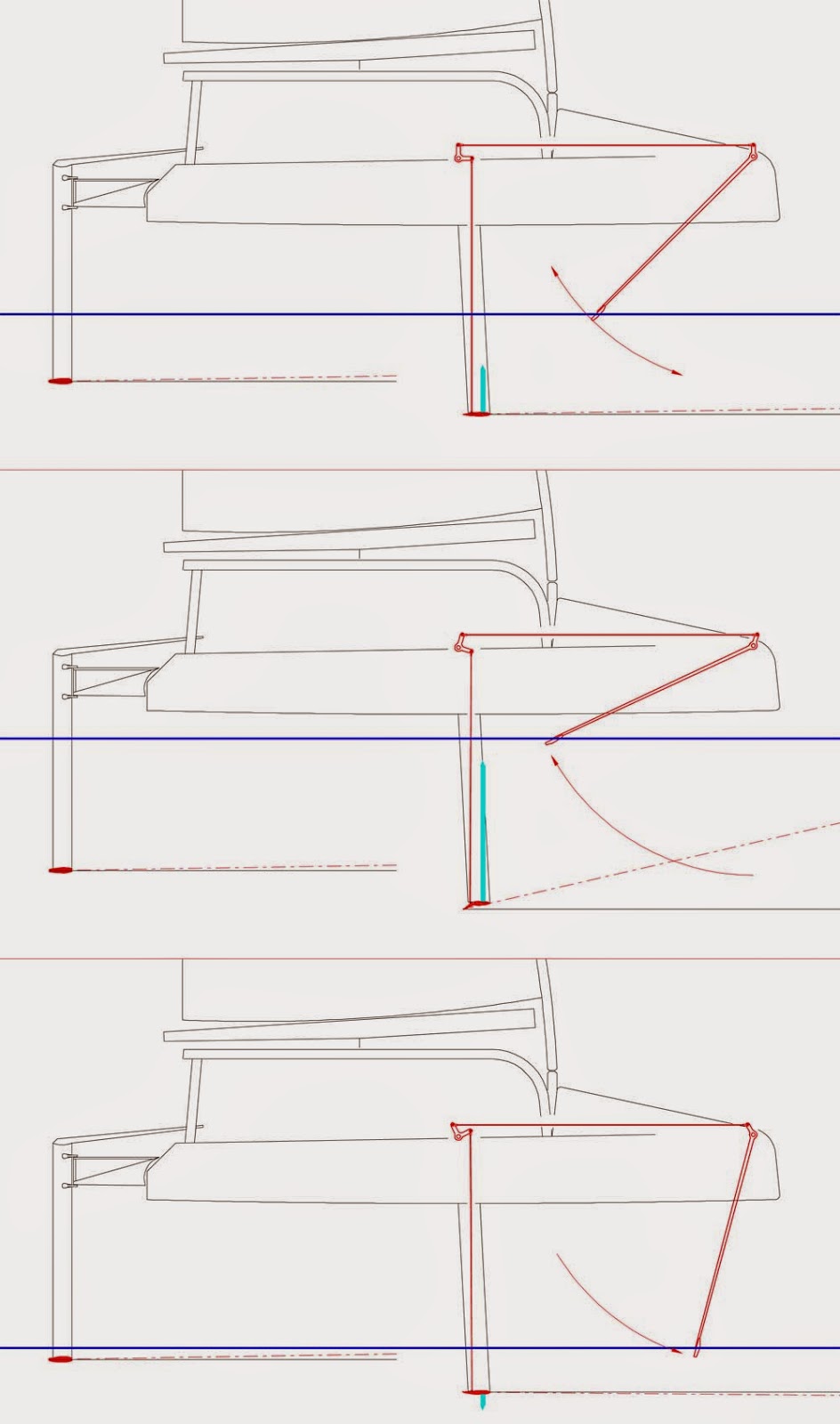
Looking again at the Moth, we can see an effective mechanical solution.
The bow wand senses the water surface and adjusts the camber of the main foil by actuating its flap through cranks and push/pull rods.
At lower ride heights it increases the camber and hence the lift.
At higher ride heights it reduces camber by aligning the flap closer to the chord line of the foil.
Fully foiling multihulls such as the Hydroptere are stable in pitch because they use a T foil on the rudder(s).
They have some stability in ride height by virtue of the fact that less and less of the main foils is in the water as ride height increases.
Foil assisted A Cats without a horizontal surface on the rudder cannot be stable in pitch.
Curved foils also cannot be stable in ride height because their dihedral angle increases with ride height.
Angled foils could possibly be stable in ride height in a way analogous to the Hydroptere setup but they have higher interference drag and it would be difficult to get sufficient horizontal projected area within the inboard bounds of the ‘foil box’ mandated by the A Cat rule. Though this is certainly an avenue worth exploring.
 |
| Spectacular flat water capsize. Probable cause is a sudden loss of foil lift due to dynamic instability. Image credit unknown |
Addressing the issue of dynamic stability is the key to unlocking the next step in performance.
Some experimentation in the class is already bearing fruit: novel foil geometries and different shapes and sizes of horizontal surfaces on the rudders are becoming an increasingly common sight.
We are looking carefully at some very promising alternatives as we develop our new A Cat.