I have added ‘FAQ’ as a label so in future these posts can be filtered out by those (fellow sailing nerds) who are interested…
Why Ls on the rudders instead of Ts or ‘+’ s?
A single bent foil has no intersections so there is no interference drag (strictly speaking there is still some interaction between the pressure fields, but it is much smaller since the transition is very gradual).
Crossing two foils is very costly in terms of drag because of the way the pressure gradients combine and interact.
Basically, the low pressure peak near the main foil leading edge combines with the corresponding similar peak on the intersecting second foil and the two amplify.
Since flow speed is related to pressure, this spike in the pressure distribution is also a radical change in flow velocity.
Accelerating the mass of any fluid involves an expenditure of energy (F=ma) that comes from the total kinetic energy of the boat which is therefore diminished… In other words redirecting water around an intersection between two bodies is draggy. The tighter the included angle the worse the drag penalty.
In some applications intersections are unavoidable, so to minimise the damage designers arrange them with intervening bodies that basically smooth out the transition by spacing the working sections of the intersecting foils apart (in three dimensions) with surfaces locally orthogonal to their respective spans.
 |
| An assortment of Moth horizontal T foils with junction bulbs. The bulbs smooth out pressure peaks and may even be designed to create destructive interference: A high pressure area in the bulb can be made to coincide with a low pressure area in a foil. The two pressure fields cancel in a way not dissimilar to the waves behind the bulbous bow of a ship. Image source :http://mothbodensee.files.wordpress.com/2012/04/2012-04-08-14-25-531.jpg |
 |
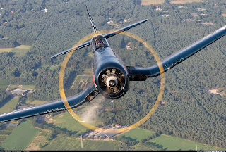
| Inverted gull wings on F4U Corsair meet fuselage orthogonal to its local surface, minimising junction drag without the need for fairings. Landing gear is placed at the kink so it can be shorter for a given prop clearance. Image source: http://www.airliners.net |
T foils are less penalising than ‘+’ foils as only three bodies intersect instead of four.
In some applications + foils are warranted when other advantages are sought. Examples of this are 14′ skiff rudders where the distance from the foil to the water surface (the stern wave) is critical. Also foil assisted multihulls optimised to have the windward rudder winglet exit the water at small heel angles. Though in the latter case a different area distribution is usually a better solution.
 |
| T tail bulb visible on an Ilyushin Il-62. Image source: http://www.airliners.net |
Another way to minimise interference drag where intersections are unavoidable is to stagger the two foils longitudinally. Especially if the foil chord dimensions are different, this can help to make sure that the pressure peaks on the two foils do not coincide. This solution requires a good understanding of the operating envelope of the foils because the pressure peaks do move around with varying speed and AoA.
 |
| Horizontal tail surface staggered ahead of vertical. Image source |
Structure
For relatively lightly loaded applications, an L is structurally much more efficient since the fibres are continuous across the two foils.
In theory a T can be engineered with very little bending moment if the horizontal foil is symmetrical about the vertical. However, on a boat that sails with heel and leeway, the load will not always be identical for both sides. Any difference will impose a bending stress on the junction which will have to be engineered accordingly.
It is possible to engineer the junction to withstand the uneven forces however, for a given material/construction, an L will always be lighter and cheaper to build accurately.
For a given span, the L solution allows the rudder to be placed further outboard, leaving the horizontal foil as an uninterrupted span (all the way in to the centreline exclusion zone in the A Class).
Placing the horizontal foil entirely on the low pressure side of the leeward rudder (the one that does more work to resist leeway) actually increases the efficiency of the rudder, partly offsetting the drag penalty associated with winglets at upwind speeds, when they are not vital to longitudinal stability.
 |
| Blended winglet on a commercial airliner. Image source: http://www.boeing.com/commercial/aeromagazine/articles/qtr_03_09/article_03_1.html |
The bend at the bottom of our rudders is not 90 degrees. The primary reason is consideration of three dimensional effects to do with stability. There is a coupling of rudder sideforce and vertical lift, tuned to help maintain stability at all times, especially when bearing away.
As a secondary benefit the leeward winglet remains horizontal even when heel angle exceeds hull cant angle (when the leeward hull is heeled to leeward).
Since the winglets are not horizontal when the boat is level, the rudders are legal when pulled right up behind the hull.
Even if optimum area turns out to be much smaller than expected, angling the winglets allows a longer span and thus a higher aspect ratio for the same area.
Practical Considerations
We found that it is easier (still not easy but easier) to shed seaweed from L rudders than from intersecting T rudders.
The debris has some chance of slipping off the end of the L rudder, while it is much more constrained on a T or + arrangement.
Using Ls combined with cassettes has several advantages such as constant compensation, precise control over winglet AoA, and the ability to partially retract (and now reverse) the rudder while maintaining efficient steerage.
